
CM4 / CM5 Gateway Carrier Board
Ready for prototype manufacturingA carrier board for the Raspberry Pi Compute Module 4 and Compute Module 5, built for industrial gateway and edge roles.
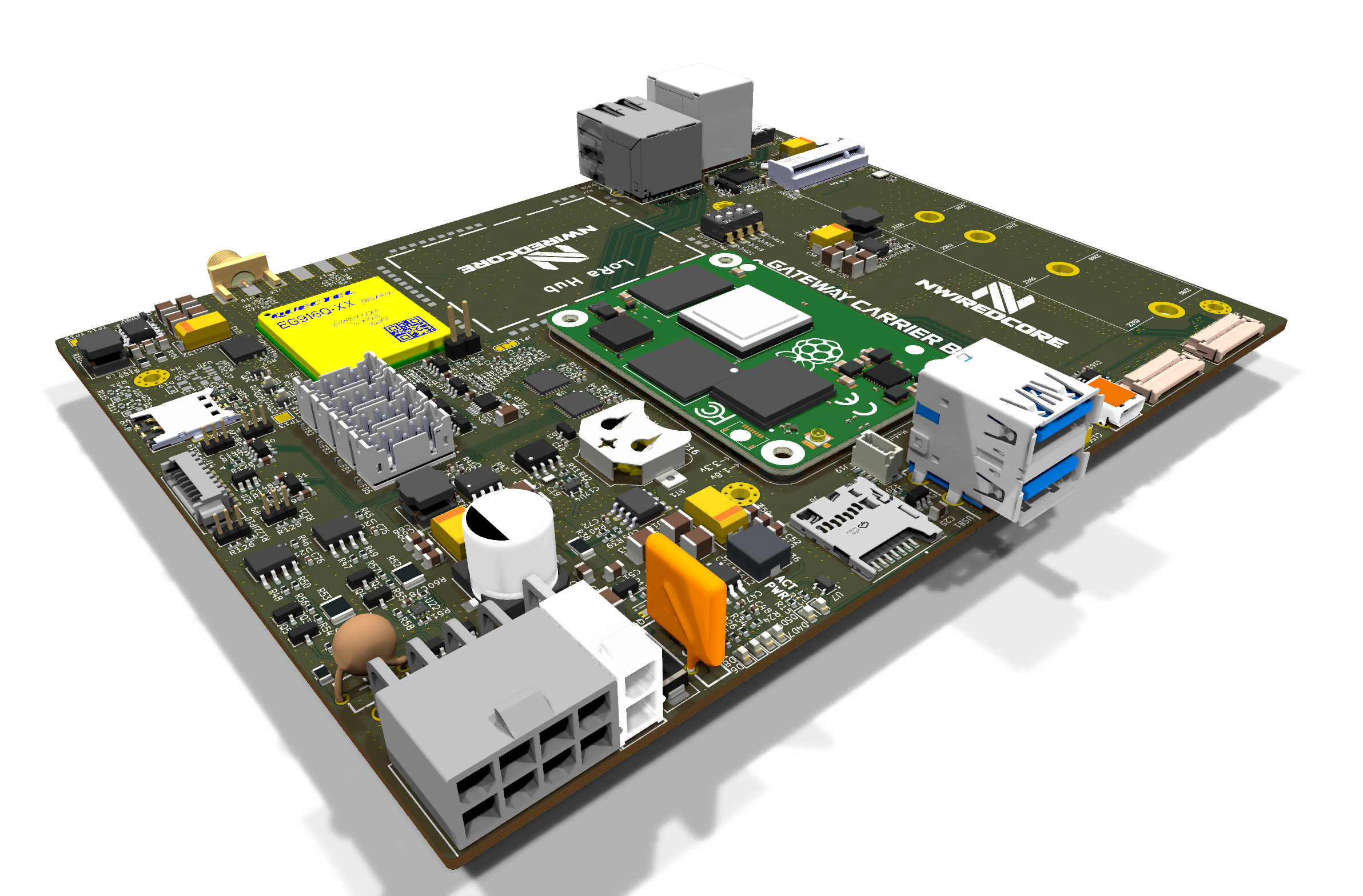
Shown with Raspberry Pi Compute Module 4 installed. The carrier board supports CM4 and CM5; Compute Module is not included.
What it is
The CM4 / CM5 Gateway Carrier Board turns a Raspberry Pi Compute Module into a wired-and-cellular industrial gateway. It pairs Gigabit Ethernet and NVMe / microSD storage with an LTE modem (Nano-SIM plus an onboard eSIM IC), two independent RS-485 ports, universal and vibration sensor inputs, and MIPI camera / display plus micro-HDMI, on a board built around a wide industrial DC input. The base configuration shown uses an LTE modem without GNSS; GNSS is available through a compatible LTE / GNSS modem variant. Engineering design is complete — schematic, PCB layout and the manufacturing package (Gerbers, BOM, CPL) — and the board is ready for prototype manufacturing. No prototypes have been built or tested yet.
Current stage
Hardware design and the full manufacturing package are complete. Building and validating the first physical prototype is the next step. No prototypes have been built or tested yet.
Completed
- Hardware architecture
- Schematic / PCB design
- Manufacturing package
Next
- Prototype manufacturing
Configurations
The Gateway Carrier Board is the base product. It has no onboard LoRa. GNSS can be added either through a compatible LTE / GNSS modem or through the separate NWIREDCORE LoRa Hub. Multi-channel LoRa connectivity is provided only by the separate LoRa Hub.
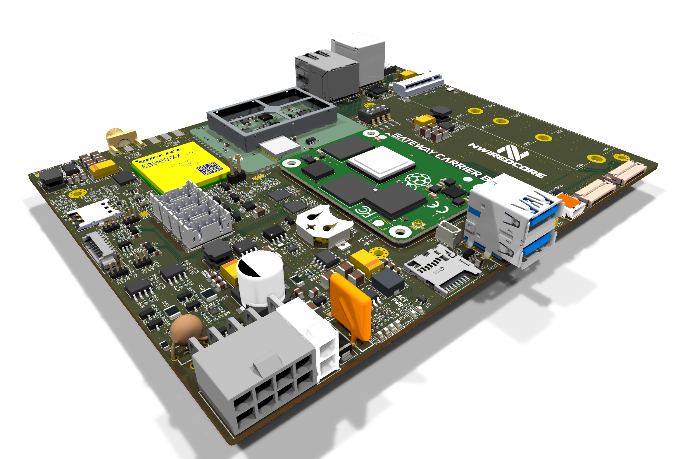
The LoRa Hub is a separate companion module and is not included in the base Gateway configuration.
Board views
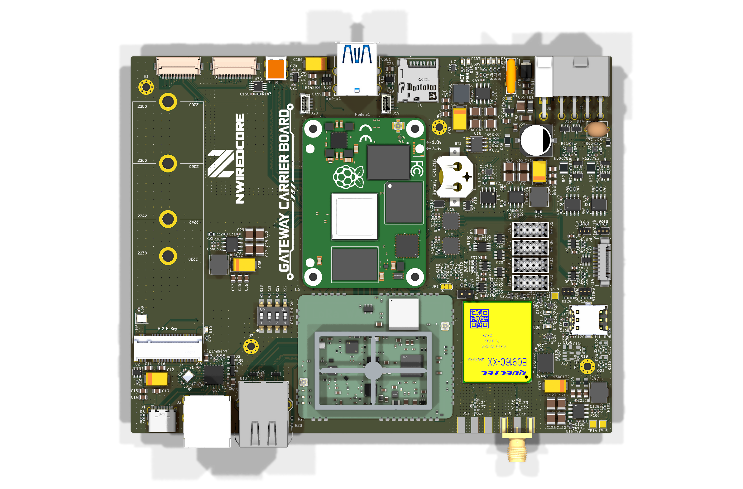
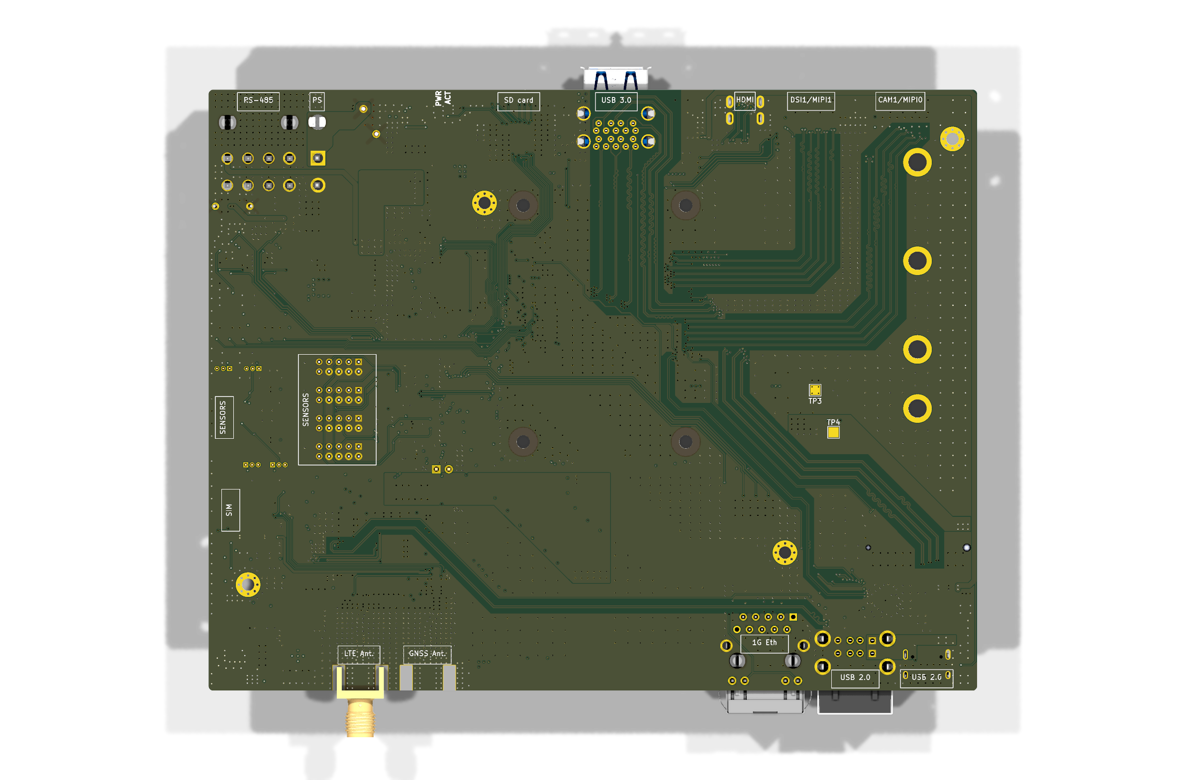
Top and bottom of the board (KiCad ray-traced renders). The LoRa Hub is a separate companion module.
Core capabilities
Current design intent. Individual items may still change during prototype bring-up and validation.
- 01Raspberry Pi Compute Module 4 / 5 (CM4 / CM5)
- 02Gigabit Ethernet
- 03LTE modem — Nano-SIM + onboard eSIM
- 04M.2 NVMe SSD, 2280 + microSD
- 052 × independent RS-485 ports
- 064 × universal digital sensor inputs
- 074 × dedicated vibration sensor inputs
- 08Industrial DC input, approx. 7.5–24 V DC
- 093 × USB 2.0 — 2 × Type-A + 1 × Type-C
- 102 × USB 3.0 Type-A with CM5
Current design specification
Current design specifications. Some details may change after prototype bring-up and validation.
Compute & storage
- Raspberry Pi Compute Module 4 / 5 (CM4 / CM5)
- M.2 NVMe SSD, 2280
- microSD
Network & connectivity
- Gigabit Ethernet
- LTE modem
- Nano-SIM holder
- Onboard eSIM IC
- LTE antenna connector
- Current Gateway modification: no GNSS
- Optional GNSS with a compatible LTE / GNSS modem variant
- 2 × USB 2.0 Type-A
- 1 × USB 2.0 Type-C
- 2 × USB 3.0 Type-A when CM5 is installed
Field I/O & sensors
- 2 × independent RS-485 ports
- 4 × universal digital sensor inputs
- 4 × dedicated vibration sensor inputs with programmable trigger threshold
Display / camera
- Micro-HDMI
- MIPI camera / display connectors
Power
- Industrial-oriented DC input
- Approximately 7.5–24 V DC design range
Intended applications
Target application areas for the current design.
- Industrial gateways
- IoT gateways
- Remote monitoring
- Telemetry
- Edge computing
- Automation
- Custom embedded systems
Current opportunities
Current partnership opportunities related to this product. Full details are available on the Partners page.
CM4 / CM5 Gateway Carrier Board — prototype manufacturing
We are looking for an electronics manufacturing partner to fabricate and assemble the first prototype batch of the Gateway Carrier Board. The hardware design and full manufacturing package (Gerbers, BOM, CPL) are complete.
Apply for thisGateway development and launch support
We are looking for early partners to support prototype bring-up, software and firmware development, integration, validation and initial deployments. Support may include funded engineering work, prototype purchase commitments, integration contracts, development sponsorship or a paid pilot.
Apply for thisHardware distribution and regional integration
Broader distribution and regional integration relationships across the NWIREDCORE hardware portfolio are expected to become more relevant after prototype validation and initial pilot deployments.
Not accepting applications yet.
Where this comes from
NWIREDCORE's reusable hardware evolved from the engineering work behind the Remote Monitoring Platform.
The Gateway originated as the edge-computing and connectivity component of the Remote Monitoring Platform: the local hub that collects sensor data, runs local services and connects a site to the wider network.
Explore the Remote Monitoring PlatformRoadmap
- Hardware architectureCompleted
- Schematic / PCB designCompleted
- Manufacturing packageCompleted
- Prototype manufacturingNext step
- Assembly and bring-upUpcoming
- Hardware testing and validationUpcoming
- Software / firmware and system integrationUpcoming
- Design revision if requiredFuture
- Pilot / small production batchFuture
The engineering design package is complete: schematic, PCB layout and manufacturing outputs (Gerber files, BOM and CPL / placement files). The next milestone is prototype fabrication, assembly and bring-up. Specification values above are the current design intent and may still change during bring-up and validation.
Build on this design
This design can be a starting point for a custom project: adapted interfaces, sensors, power, communication or firmware, instead of starting from zero.
Interested in this project?
Register your interest to receive prototype, testing and future availability updates. No payment or purchase commitment.
Prefer email? [email protected]